Android Asymmetric Multiprocessing on Toradex Colibri i.MX7D
Android Asymmetric Multiprocessing on Toradex Colibri i.MX7D
Introduction
This technical note describes a demo application we have been working on for reading and displaying data from an Inertial Measurement Unit, running on a heterogeneous asymmetric system based on the NXP i.MX7D. Workload is distributed across the cores: the MCU (running FreeRTOS) takes samples from the IMU board (i2c) and periodically sends data to the MPU over a RPMsg channel. Accelerometer, gyroscope and magnetometer data are then logged on the MPU, running Android Nougat, by a native C (NDK) user-space application.
The demo is composed by two parts: one FreeRTOS app running on the MCU which handles sensor sampling and one Android user-space executable. Inter-core data exchange is enabled by the RPMsg framework. The Android executable can be configured to either request the MCU to send all components of the accelerometer, magnetometer and gyroscope vectors or only the norm of the three vectors.
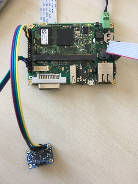
The demo has been developed on the Toradex Iris carrier board with the Colibri i.MX7 SoM. This SOM features the i.MX7 processor, which couples a dual Cortex-A7 and a Cortex-M4 on the same SoC. A diagram of the i.MX7D structure is shown below:
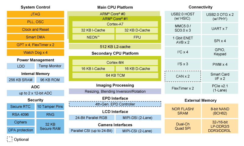
In the i.MX7 architecture:
- The Cortex-A7 is the master, meaning that it is responsible for booting the Cortex-M4 core (i.e. starting clocks, writing firmware address information into M4 bootROM, put M4 out of reset). Once started, both cpus run independently, executing different instructions at different speeds.
- The two different cores communicate between each other. In hardware, this is enabled by the Messaging Unit. In software this is enabled by RPMsg and the OpenAMP framework.
- Both cores access the same peripherals, therefore a mechanism for avoiding conflicts is required. In the i.MX7 architecture, processor isolation is ensured by the Resource Domain Controller.
More detailed information about the Messaging Unit and the RDC components can be found in the i.MX7D Reference Manual (Section 3.2 and 4.3).
The kernel and BSP versions used in this demo are:
- Android 7.1.2 for Colibri i.MX7 (see here for reference)
- Modified u-boot with support for ELF binaries for M4
- Android kernel 4.9.76 patched to support rpmsg char device
- FreeRTOS BSP 1.0.1 available here
Demo overview
The following diagram shows an overview of the overall application:
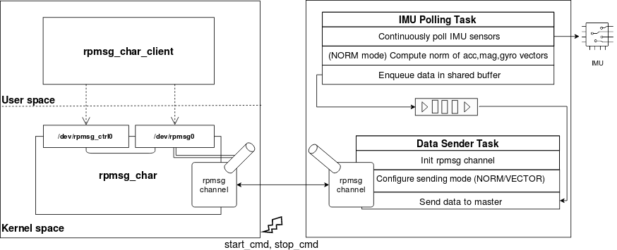
The right side represents the FreeRTOS application running on the MCU, while the left side represents the Android application running on the MPU.
IMU data sampling (FreeRTOS app)
This section describes the FreeRTOS application running on the the remote core (right side in the diagram of the previous section).
The application can be configured in two different modes:
- NORM mode: only the norm (module) of the accelerometer, magnetometer and gyroscope vectors are sent to the master core
- VECTOR mode: all components of the accelerometer, magnetometer and gyroscope vectors are sent to the master core
The sending mode is set/switched by the master core (Cortex-A7) through a specific RPMsg message.
The application is composed of two asynchronous tasks, which share a queue where data is buffered:
-
IMU Polling Task
- when NORM mode is set, continuously collects samples from the IMU, elaborate the accelerometer, magnetometer and gyroscope data and puts the results in a buffer queue
- when VECTOR mode is set, continuously collects samples from the IMU and enqueues samples in a buffer queue
-
Data Sender Task
- initializes the RPMsg channel
- handle the receiving of the RPMsg message containing the sending mode configuration (either NORM or VECTOR)
- set the appropriate sending mode and sends data to the master over the RPMsg channel
Inter-core signaling is used to make the MCU aware of the MPU status and to suspend data flow when not needed. To achieve this, two general purpose interrupts (made available by the i.MX7 Messaging Unit) are triggered by the master core towards the remote core:
- start_cmd is used to signal that the master has created the endpoint interface (i.e. data flow can be started)
- stop_cmd is used to signal that the master has closed the endpoint interface (i.e. data flow can be suspended)
The control flow of the data sender task is shown below:

Note: Only the state diagram of the data sender task is shown, since IMU polling task keeps staying in the same "poll-elaborate data-enqueue data in buffer" loop during all the remote core lifecycle.
- S0: RPMsg channel is down
- S1: RPMsg channel is up, waiting for RPMsg message from master with required sending mode configuration (NORM/VECTOR)
- S2: Sending mode set, waiting for master to be ready
- S3: Sending data to the master through RPMsg channel
The first transition occurs with the RPMsg channel creation. Then the task waits for the master to send an RPMsg message with the desired configuration, which configures the format so that data is elaborated accordingly. When the start_cmd interrupt arrives, the data sender task starts sending data to the master core. If stop_cmd is received, the task suspends the data flow towards the master, resetting the current state, and going back to state S1.
IMU data logging on Android
This section describes the Android executable running on the the master core (left side in the overview diagram).
Data is exchanged through the two cores over an RPMsg channel. The RPMsg character driver is used to export the master RPMsg endpoint as a character device, enabling interaction with the remote device from user-space. The rpmsg_char_client user-space application interacts with the character devices in order to initialize the endpoint interface device, read incoming data and log to a text file.
Note: the RPMsg character driver was introduced in Linux kernel version 4.11. For the purpose of this demo, the driver has been backported to Android kernel version 4.9.
The rpmsg_char_client executable supports two options:
-c [norm|vector]indicates whether to log all components of the vector or only its norm-d [path]path to where the text file containing samples is saved
When rpmsg_char_client application is started, the RPMsg endpoint on the master side is created. An RPMsg message is sent to the remote core, with the sending mode configuration set by the -c parameter (by default, if no configuration is set by the user "norm" is set). Incoming data is read and can be eventually logged on a text file which is saved on the location specified by the -d option (by default it is saved in ~/data/local).
When the application is started, the configuration message is sent and start_cmd is triggered; when the application is closed, the endpoint is destroyed and stop_cmd is triggered.

- S0: RPMsg channel is down
- S1: RPMsg channel is up, /dev/rpmsg0 is created
- S2: RPMsg channel is up, endpoint created, data is dumped into a log file
A first transition occurs when the RPMsg char driver is probed. By opening the /dev/rpmsg0 character device, the RPMsg endpoint is created. The configuration message is sent by writing on the /dev/rpmsg0 character device, which is the interface device to the RPMsg endpoint. Data is then read from the /dev/rpmsg0 device and logged to a text file. Finally, the RPMsg endpoint is destroyed by closing the character device.
Note: in this first diagram the interaction with the driver control interface (i.e. /dev/rpmsg_ctrl0) is not shown for simplicity.
Parameters
The MCU polls the IMU sensor board every 10ms and uses a buffer queue with a length of 300 elements to store the accelerometer, magnetometer and gyroscope vector components or norms (depending on the configuration). Every 100 ms, 10 items are dequeued from the buffer and sent to the MPU over the RPMsg channel to the master endpoint.
Video of the demo
The video shows the demo in action. The left part shows the prompt of Android running on the Cortex-A7 (i.e. the master core), while the right part shows the output of the FreeRTOS application running on the Cortex-M4 (i.e. the remote core).
Once the system is fully booted, the user logs in on the Android shell through adb and launches the user-space executable rpmsg_char_client with the desired options. The app is launched in the "NORM" mode first, and in the "VECTOR" mode after.
The remote core sets the sending mode requested by the master and starts sending data through the RPMsg channel, as shown in the FreeRTOS application output.
On the master side, data is read and logged on the samples.txt text file.